How Can We Help?
7. Exporting Vector Data
Next we need to export the vector GIS data, but before we do, we need to edit it a little first.
We want to keep the rail, road and trail vectors separate, so we need to export them individually.
Importing vector lines into UE4 that have vertices on the boundaries of the landscape (DTM) can cause problems when clamping the spline control points to the landscape. To avoid this we can scale the AOI down slightly, so we’re exporting the vectors from an area that’s smaller than the DTM coverage. The easiest way to do this is create a ‘Buffer’ inside the AOI.
We’ll start with the road vectors.
Step 1
Create a slightly smaller area than your AOI to use to export the vectors:
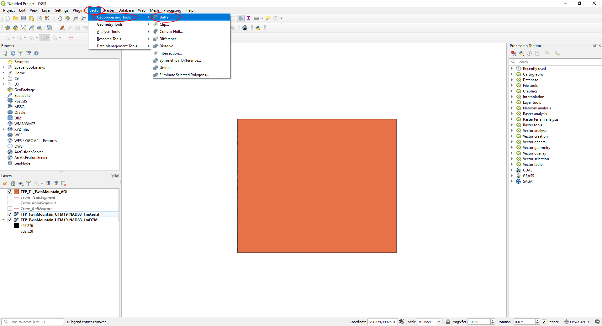
- On the main menu, click ‘Vector’, then select ‘Geoprocessing Tools’ > ‘Buffer…’
In the ‘Buffer’ window:
- In ‘Input layer’ select the layer with your AOI rectangle.
- Set ‘Distance’ to ‘-2’ (to create a buffer 2m inside the original rectangle).
- Set ‘End cap style’ to ‘Square’.
- Click ‘Run’ to create the new buffered layer.

Once created, you’ll see a ‘Buffered’ layer appear in the ‘Layers’ panel.
- <Right-click> on the layer to rename it (we’ve called ours ‘TFP_TwinMountain_AOI_Vector’.
Step 2
Clip the roads layer to the new vectors AOI created in Step 1:
- Turn the roads layer on in the ‘Layers’ panel and turn off the layer with the original AOI rectangle.
- Turn off the exported aerial and DTM layers.
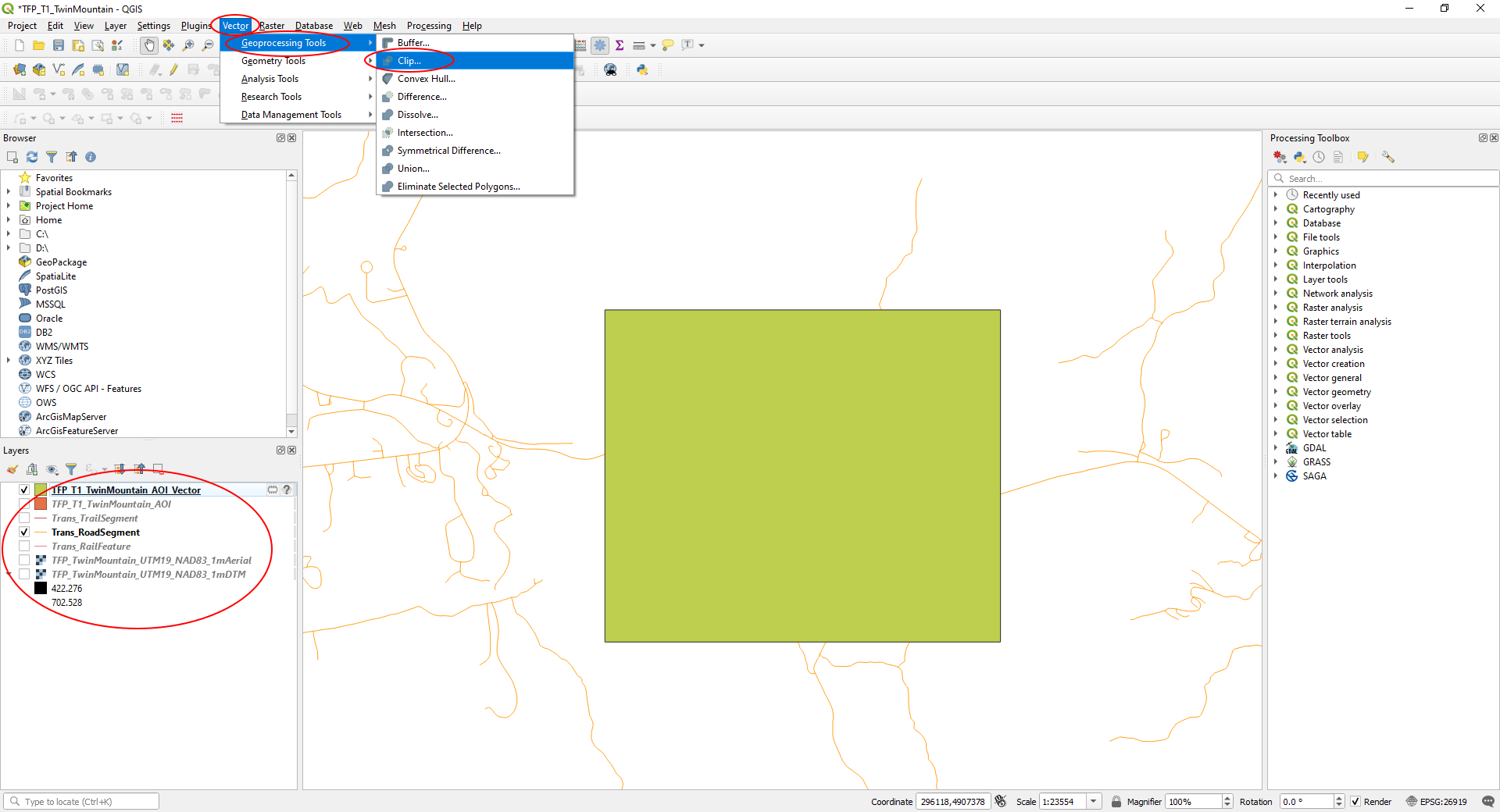
- On the main menu, select ‘Vector’ > ‘Geoprocessing Tools’ > ‘Clip…’.
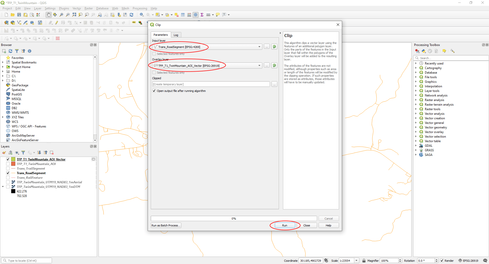
In the ‘Clip’ window:
- Set ‘Input Layer’ to your roads vector layer.
- Set ‘Overlay Layer’ to the layer containing your new AOI rectangle.
- Click ‘Run’.
Step 3
Edit the vector data:
We need to make sure the vector files are correctly set up for use as splines in UE4. A common problem is splines being broken into segments. We need to connect them together to prevent breaks in our UE4 spline meshes when we import them in to UE4.
- Turn off the roads vector source data and the vector AOI (uncheck).
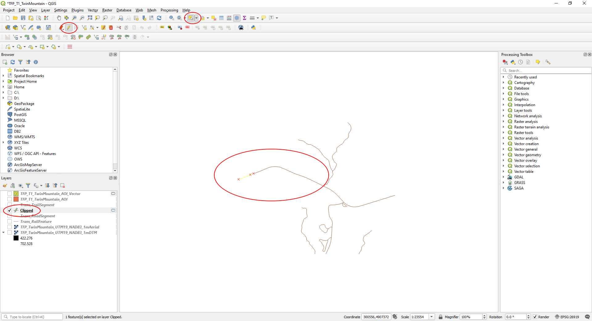
- Select the ‘Clipped’ layer.
- Click the ‘Toggle Editing’ button on the toolbar, then the ‘Select features by area or single click’ button.
- Selecting part of the roads vector, you can see it’s separated into discreet segments.
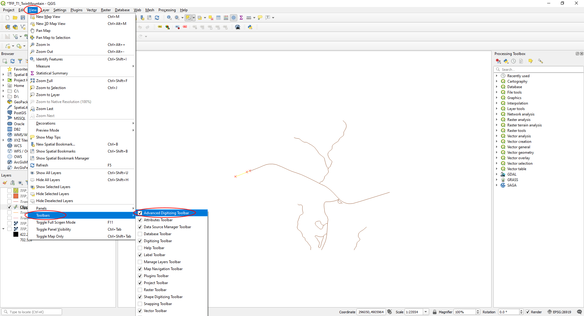
Turn on the ‘Advanced Digitizing Toolbar:
- on the main menu, select ‘View’ > ‘Toolbars’ > ‘Advanced Digitizing Toolbar’.
Connect discreet line segments:
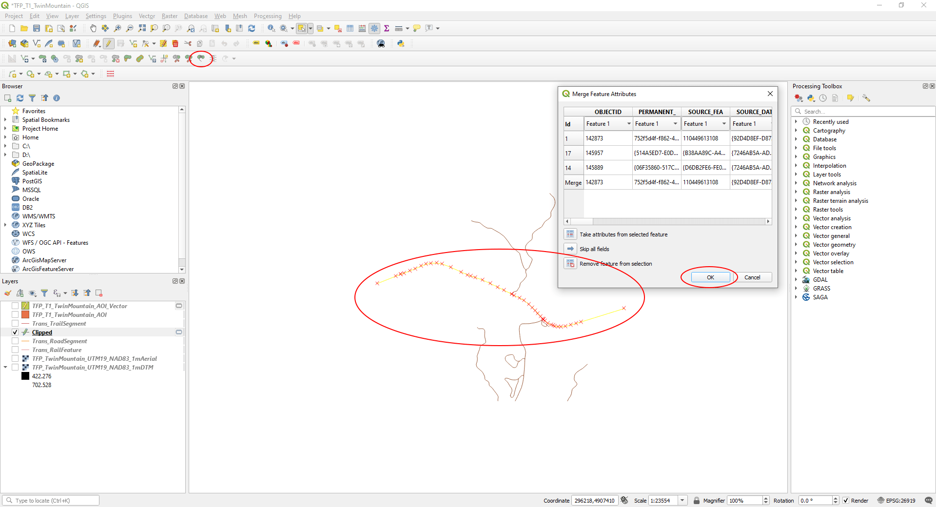
- With the ‘Select features by area or single click’ button still selected, hold the <shift> key and click all line segments that should be connected (you can see the road should be continuous).
- On the ‘Advanced Digitizing Toolbar’, click ‘Merge Selected Features’.
- Click ‘OK’ on the ‘Merge Feature Attributes’ window that appears.
- Repeat this for any other roads that aren’t connected correctly.
Step 4
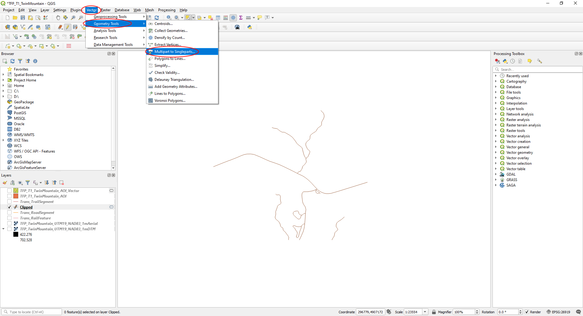
Convert multi-part line-strings to single-part:
- On the main menu, select ‘Vector’ > ‘Geometry Tools’ > ‘Multipart to Singleparts…’.
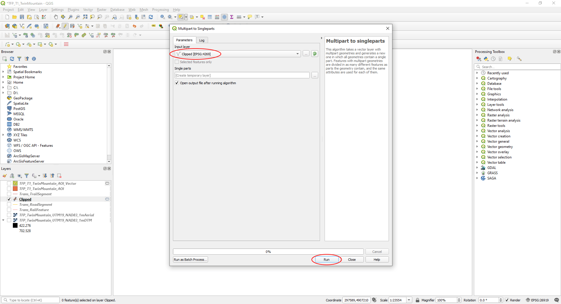
On the ‘Mulitpart to Singleparts’ window:
- Make sure the ‘Clipped’ layer containing the features you’ve edited is selected.
- Hit ‘Run’.
Step 5
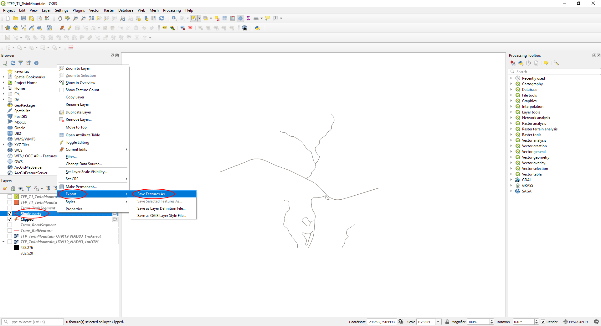
Export the road layer:
- <Right-click> on the new ‘Single Parts’ road layer in the ‘Layers’ panel, then ‘Export’ > ‘Save Features As…’
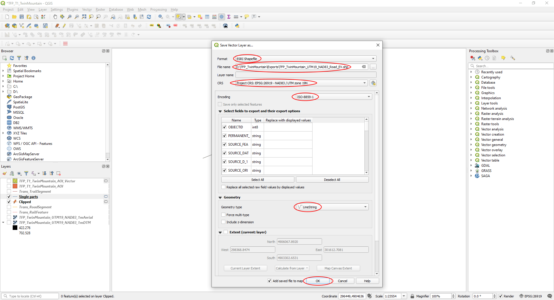
In the ‘Save Vector Layer as…’ window:
- Set ‘Format’ to ‘ESRI Shapefile’.
- In ‘File name’ navigate to the folder you exported the DTM and aerial to and give your road vectors a filename.
- Set ‘CRS’ to ‘Project CRS’
- Under ‘Geometry’, change ‘Geometry Type’ to ‘LineString’.
- Click ‘OK’.
Close the ‘Single parts’, ‘Clipped’ and source road vector files:
- In the ‘Layers’ panel, select the ‘Clipped’ and source rail vector files.
- <Right-click>, then ‘Remove Layer…’
- ‘Discard’ any changes if you see a ‘Stop Editing’ window – we’ve already exported the data we need.
- ‘OK’ the ‘Remove layers and groups’ pop-up.
Step 6
Repeat Steps 3 to 5 for the rail and trails vector files.
Your exported data folder should look something like this:
